
Administering MAX TNT Slot Cards
This chapter covers the following topics:
Overview
Typical system administration tasks for the MAX TNT slot cards include viewing status information, removing a slot card configuration, and disabling lines. For information about managing the MAX TNT system, see Chapter 2, "MAX TNT System Administration."
Viewing installed slot cards
The Show command displays information about the slot cards installed in the MAX TNT and the status of each card. In a multishelf system, the Show command displays cards in all shelves the system. You can also use the Show command for a particular slot card. For an example, see Viewing information about a particular slot card.
admin> showThe output lists the physical address of each slot in which an expansion card is installed. The address is in the form {shelf slot item}. Each listing also shows the status of the card and the type of card installed.
Shelf 1 ( master ):
{ shelf-1 slot-1 0 } UP 4ether-card
{ shelf-1 slot-3 0 } UP 48modem-card
{ shelf-1 slot-4 } OCCUPIED
{ shelf-1 slot-15 0 } UP 192hdlc-card
{ shelf-1 slot-16 0 } UP 8t1-card
{ shelf-9 slot-1 0 } UP 4ether-card
{ shelf-9 slot-2 0 } UP 192hdlc-card
{ shelf-9 slot-15 0 } UP 48modem-card
{ shelf-9 slot-16 } OCCUPIED
{ shelf-9 controller 0 } UP shelf-controller
The status can be reported as follows:
The Show command can report the following types of slot cards:
Viewing information about a particular slot card
To use the Show command for information about a particular command, add the shelf and slot-card numbers as arguments. For example:
admin> show 1 15
Shelf 1 ( standalone):
    { shelf-1 slot-15 0 }      UP       4ether-card:
    { shelf-1 slot-15 1 }      UP         ethernet-1
    { shelf-1 slot-15 2 }      UP         ethernet-2
    { shelf-1 slot-15 3 }      UP         ethernet-3
    { shelf-1 slot-15 4 }      UP         ethernet-4
    { shelf-1 slot-15 5 }                 100-Base-T
Opening a session with a slot card
To open a session with a slot card, use the Open command as in the following example:
admin> open 1 7where 1 is the shelf number and 7 is the slot number.
On the master shelf of a multishelf system, you can open a session with a slave shelf. For example:
admin> open 3 17You cannot use the Open command from the slave shelf.
After you have established a session with the card, the prompt changes to indicate the type of card, its slot number, and its shelf number. To list the commands available on the card, enter a
? or help, as in the following example:
t1-1/1> ?For information about the card-level commands, see the MAX TNT Reference Guide.
? ( user )
auth ( user )
cbcardif ( debug )
cbsnmptrap ( debug )
cbStats ( debug )
checkd ( debug )
clear ( user )
clock-source ( diagnostic )
debug ( diagnostic )
debugd ( debug )
display ( debug )
dp-decode ( debug )
dp-ram-display ( debug )
dpram-test ( debug )
dspBypassClients ( debug )
dspDial ( debug )
dspSetDddTimeslot ( debug )
fakeCalledId ( debug )
fakeClid ( debug )
fe-loop ( diagnostic )
fill ( debug )
frreset ( debug )
[More? <ret>=next entry, <sp>=next page, <^C>=abort]
To exit the session with the card, enter
quit, as in the following example:
t1-1/1> quit
Changing a slot state
To force a change in the state of a slot, use the Slot command, as shown in the following examples.
admin> slot -d 1 3To bring a slot up:
slot 1/3 state change forced
admin> slot -u 1 3You cannot change the state of a slave shelf controller by using the Slot -u or Slot -d commands.
slot 1/3 state change forced
Changing a device state
To force a change in the state of a device, use the Device command, as shown in the following examples.
admin> device -d {{1 3 6} 24}
slot 1/3 state change forced
To bring a device back up:
admin> device -u {{1 3 6} 24}
slot 1/3 state change forced
Removing a slot card and its configuration
MAX TNT slot cards are hot swapable. When you remove a card, the system retains its configuration. This enables you to re-install the card or install another of the same type in the same slot, without reconfiguring the system or uploading a backup configuration. One side-effect of this feature is that the NVRAM used to store configuration information is not cleared when a card is removed, until you explicitly clear the configuration.
admin> show 1 13The NONE status indicates that the card was removed but its profiles have been saved. The MAX TNT remembers that a card was in that slot and saves its profiles until a card of a different type is installed in the same slot, or until the administrator enters the Slot -r command, as in the following example:
Shelf 1 ( master ):
{ shelf-1 slot-13 0 } NONE slot-card-8t1:
{ shelf-1 slot-13 1 } t1-line-1
{ shelf-1 slot-13 2 } t1-line-2
{ shelf-1 slot-13 3 } t1-line-3
{ shelf-1 slot-13 4 } t1-line-4
{ shelf-1 slot-13 5 } t1-line-5
{ shelf-1 slot-13 6 } t1-line-6
{ shelf-1 slot-13 7 } t1-line-7
{ shelf-1 slot-13 8 } t1-line-8
admin> slot -r 13In either case, all the old profiles associated with the slot are deleted. If a different type of card is inserted, appropriate new profiles are created.
slot 1/13 removed
Viewing the clock source for a slot card
The Clock-Source command can be run on the shelf controller or on an individual card, as in the following example on a T1 card:
admin> open 1 1
t1-1> clock-sourceSources with layer 2 up, which are preferred, are marked with an asterisk. For information about configuring the clock source see the MAX TNT Hardware Installation Guide.
Master line: 3
Source List:
Source: line 3 Available* priority: 1
Recovering from a failed slot-card installation
If you installed a new slot card before upgrading the system software, and the slot card does not come up properly, there are two ways to recover:
To recover from a failed slot-card installation by this method:
admin>save network bonzo 971001This saves the configuration to a file named 971001 in the TFTP home directory on a host named
bonzo.
admin>nvramclear
admin>load config network bonzo 971001This restores the configuration from a file named 971001 in the TFTP home directory on a host named
bonzo.
Removing the slot card
To recover from a failed slot-card installation by removing the slot card:
admin>save network bonzo 971001 t1This saves the configuration of all the T1 profiles to a file named 971001 in the TFTP home directory on a host named
bonzo.
admin> slot -d 1 1This disables the slot card in shelf 1, slot 1.
admin> slot -r 1 1
admin> slot -u 1 1
admin>load config network bonzo 971001This restores the configuration from a file named 971001 in the TFTP home directory on a host named
bonzo.
Displaying line status
To display the activity of the MAX TNT WAN lines, enter the Line command:
admin> line [all|enabled] [top|bottom]where
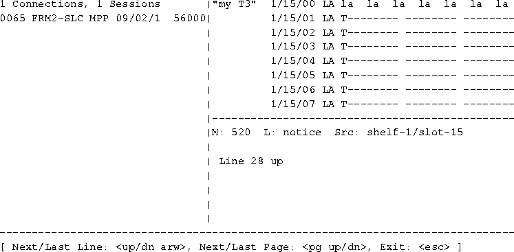
Figure 3-1. Example of a T3 card line-status window
[Next/Last Conn:<dn/up arw>, Next/Last Page:<pg dn/up>,Exit: <esc>]The message indicates the key sequences you can use for displaying additional information in the line status area. The Down Arrow and Up Arrow keys display the next and previous T1 line in the list, respectively. The Page Down and Page Up keys display the list a screen at a time.
When the line-status mode message is displayed, the system prompt does not appear at the bottom of the window. Press the Escape key to exit this mode and return to the system prompt.
Line status information includes the following identifiers and codes:
Code |
Description |
|---|---|
E
|
E1 line
|
I
|
T1 PRI signaling
|
N
|
All other NFAS types
|
P
|
NFAS Primary
|
S
|
NFAS Secondary
|
T
|
T1 inband signaling
|
Administering Ethernet cards
For all Ethernet interfaces except the shelf controller, the MAX TNT detects and flags changes in the interface link-state. You can enable a feature in the Ethernet profile that causes automatic routing table updates based on physical link-state changes. Routes to a disabled (down) interface are deleted from the IP routing table, so alternative configured routes can be used instead, and the routes are added again when the interface comes back up. You can also choose to administratively down a LAN interface by disabling its Ethernet profile.
ETHERNET {shelf-N slot-N item-N}
   enabled = yes
   link-state = up
   link-state-enabled = no
An interface may also be disabled by using the Ifmgr command, or it may be marked as down by the Ethernet driver when Link-State-Enabled is Yes and Link-State is Down.
To enable an interface, set the Enabled parameter to Yes (the default), or use the Ifmgr Up option. Note, however, that if there are physical problems with the interface, specifying the interface as up might not enable it.
To disable an interface with the Ifmgr command, proceed as in the following example:
admin> open 1 4
ether-1/4> ifmgr
ether-1/4> ifmgr -d
if  slot:if  u p ifname   mac addr      local-addr
--------------------------------------------------------------
000 0:00:000 *   pb0      000000000000 0.0.0.0/32
001 1:17:011 *   ie1-4-1  00c07b6d23f0 11.1.1.1/32
002 1:17:013 *   ie1-4-2  00c07b6d23f1 11.1.2.1/32
003 1:17:015 *   ie1-4-3  00c07b6d23f2 11.1.3.1/32
004 1:17:017 *   ie1-4-4  00c07b6d23f3 11.1.4.1/32
005 1:17:019 *   ie1-4-5  00c07b6d23f4 11.1.5.1/32
<end>
ether-1/4> ifmgr down ie1-4-1The Ifmgr display indicates that the interface is disabled by displaying a dash instead of an asterisk in the Up column (
u):
ether-1/4> ifmgr -d
if  slot:if  u p ifname   mac addr      local-add
------------------------------------------------------------------
000 0:00:000 *   pb0      000000000000 0.0.0.0/32
001 1:17:011 -   ie1-4-1  00c07b6d23f0 0.0.0.0/32
002 1:17:013 *   ie1-4-2  00c07b6d23f1 11.1.2.1/32
003 1:17:015 *   ie1-4-3  00c07b6d23f2 11.1.3.1/32
004 1:17:017 *   ie1-4-4  00c07b6d23f3 11.1.4.1/32
005 1:17:019 *   ie1-4-5  00c07b6d23f4 11.1.5.1/32
<end>
To mark an interface as up, enter a command similar to the following:
ether-1/4> ifmgr up ie1-4-1
ie1-12-1 (the default profile), and the second is named ie1-12-1-1:
admin> ifmgr -d
bif slot sif u m p ifname host-name remote-addr local-addr10.5.6.7/
---------------------------------------------------------------------------
000 1:17 000 * ie0 - 0.0.0.0/32 200.168.6.188/32
001 1:17 001 * lo0 - 0.0.0.0/32 128.0.0.1/32
002 0:00 000 * rj0 - 0.0.0.0/32 128.0.0.2/32
003 0:00 000 * bh0 - 0.0.0.0/32 128.0.0.3/32
004 0:00 000 * local - 0.0.0.0/32 128.0.0.1/32
005 0:00 000 * mcast - 0.0.0.0/32 225.0.0.0/32
006 1:12 001 * ie1-12-1 - 0.0.0.0/323210.9.1.212./24
007 1:12 002 * ie1-12-2 - 0.0.0.0/32 0.0.0.0/32
008 1:12 003 * ie1-12-3 - 0.0.0.0/32 0.0.0.0/32
009 1:12 004 * ie1-12-4 - 0.0.0.0/32 0.0.0.0/32
010 1:12 005 * ie1-12-1-1 - 0.0.0.0/32
Administering T1, T3, and FrameLine cards
MAX TNT T1, T3, an FrameLine cards are all administered in much the same way. In most cases, administration of the individual T1 lines on the three cards is identical. Table 3-1 briefly describes the different methods you can use to manage the T1, T3, or FrameLine cards, and shows where each method is discussed in this manual.
Quiescing a PRI line or T1 channels
Quiescing a PRI line takes the line out of service by removing channels from service as active calls disconnect. The switch used by the carrier affects whether the line is taken out of service or busied out. For details, see the Quiesce command description in the MAX TNT Reference Guide.
Using the Maintenance-State parameter
To quiesce a line with the Maintenance-State parameter, proceed as in the following example:
admin> set line maintenance-state=yes
admin> write
T1/{ shelf-1 slot-2 1 } written
admin>quiesce -d|e|r|q|t linewhere
admin> quiesce -q {1 2 4}
QUIESCE: line 1/2/4, enable=T, isPri=T
Restoring a line or channel that has been quiesced can take up to 3.5 minutes, because only 1 service message per channel is sent to the switch, at a rate of one per second. To restore the line quiesced in the preceding example:
admin> quiesce -r {1 2 4}
QUIESCE: line 1/2/4, enable=T, isPri=T
Following is an example of quiescing a single channel:
admin> quiesce -d {{1 2 4} 1}
You cannot use FDL reporting on a line configured for D4 framing. However, you can obtain D4 and ESF performance statistics in the FDL Stats windows or the DSX MIB, even if you do not choose an FDL protocol. (For further information, see the Frame-Type parameter description in the MAX TNT Reference Guide).
To specify the type of FDL, proceed as in the following example:
admin> read t1 {1 2 1}
T1/{ shelf-1 slot-2 1 } read
admin> set fdl = [none|at&t|ansi|sprint]
admin> write
admin> t1channels - a|d|c|iwhere
-a option:
admin> t1channels -a
T1 channels available for use:To display information about which T1 channels are in use:
(dvOp dvUpSt dvRq sAdm nailg)
Channel { { 1 1 3 } 1 } (Up Idle UP UP 00000)
Channel { { 1 1 3 } 2 } (Up Idle UP UP 00000)
Channel { { 1 1 3 } 3 } (Up Idle UP UP 00000)
Channel { { 1 1 3 } 4 } (Up Idle UP UP 00000)
Channel { { 1 1 3 } 5 } (Up Idle UP UP 00000)
Channel { { 1 1 3 } 6 } (Up Idle UP UP 00000)
Channel { { 1 1 3 } 7 } (Up Idle UP UP 00000)
Channel { { 1 1 3 } 8 } (Up Idle UP UP 00000)
Channel { { 1 1 3 } 9 } (Up Idle UP UP 00000)
Channel { { 1 1 3 } 10 } (Up Idle UP UP 00000)
Channel { { 1 1 3 } 11 } (Up Idle UP UP 00000)
Channel { { 1 1 3 } 12 } (Up Idle UP UP 00000)
admin> t1channels -i
T1 channels allocated/in-use:
                                (dvOp  dvUpSt  dvRq  sAdm nailg)
  Channel { {  1  1  1 }  1 }   (Up    Assign  UP    UP   00000) I
  Channel { {  1  1  1 }  9 }   (Up    Assign  UP    UP   00006) I
  Channel { {  1  1  1 } 10 }   (Up    Assign  UP    UP   00006) I
  Channel { {  1  1  1 } 11 }   (Up    Assign  UP    UP   00006) I
  Channel { {  1  1  1 } 12 }   (Up    Assign  UP    UP   00006) I
  Channel { {  1  1  1 } 13 }   (Up    Assign  UP    UP   00006) I
  Channel { {  1  1  1 } 14 }   (Up    Assign  UP    UP   00006) I
  Channel { {  1  1  1 } 15 }   (Up    Assign  UP    UP   00006) I
  Channel { {  1  1  1 } 16 }   (Up    Assign  UP    UP   00006) I
  Channel { {  1 10 10 }  1 }   (Up    Assign  UP    UP   00005) I
admin> open 1 13Then enter the T1-Stats command. The following example shows the command's syntax:
t1-1/13> t1-statsTo view DS1-level statistics on the first line on the card:
t1-stats [ -c ] <line> get error statistics for the line
-c: reset statistics to zero
t1-1/13> t1-stats 1Table 3-2 explains the T1-Stats fields.
Line 1:
CRC Errors: 0
Frame Slips: 8
Framing Bit Errors: 0
Out of Frame Events: 0
Line Code Violations: 0
The following example shows how to view and reset the statistics to zero on line 2:
t1-1/13> t1-stats -c 2The
Line 2:
CRC Errors: 2
Frame Slips: 3
Framing Bit Errors: 0
Out of Frame Events: 0
Line Code Violations: 3
Statistics cleared.
Statistics cleared message at the end of the display indicates that the statistics have been reset to 0 (zero), because the command included the -c option.
LB (loopback) status for the line.The following examples demonstrate the use of the FE-Loop command:
To loop the CSU towards the network for the first DS1 in slot 1:
admin> open 1 1In this example, the receive side of the T1 is not bridged to the MAX TNT.
t1-1/1>
t1-1/1> fe-loop 1 in on
To turn the loopback off:
t1-1/1> fe-loop 1 in offTo send a remote loopback request to the remote CSU:
t1-1/1> fe-loop 1 out onIn this example, the receive side of the T1 is bridged to the MAX TNT.
To turn the remote loopback off:
t1-1/1> fe-loop 1 out off
For example, to manage a DS3 card on the shelf 1 in slot 15, first enter the Open command as follows:
admin> open 1 15Then, enter the DS3Link command:
t3-1/15> ds3link -optionwhere -option is one of the following:
To display alarms on the line:
t3-15> ds3link -aA display of
Loss of Signal: false
Out of Frame: false
Alarm Indication Signal: false
Idle Signal: false
Yellow Signal: false
In Red Alarm: false
C-bit parity framing: false
true for C-bit parity framing would not indicate an alarm state, but that the far end is using C-bit parity. To display and clear line error statistics:
t3-1/15> ds3link -cTo display the line state of the third DS2:
Line Code Violations: 2136611
Framing Errors: 67279
Excessive Zeros: 2098353
P-bit Parity Errors: 217318
C-bit Parity Errors: 0
Far End Block Errors: 0
DS2 1 Framing Errors: 8415
DS2 2 Framing Errors: 8415
DS2 3 Framing Errors: 8415
DS2 4 Framing Errors: 8415
DS2 5 Framing Errors: 8415
DS2 6 Framing Errors: 8415
DS2 7 Framing Errors: 8415
Statistics cleared.
      t3-1/15> ds3link -d 3
      State of DS2 3:
      Out of Frame:              false
      Alarm Indication Signal:   false
      Yellow Signal:             false
      In Red Alarm:              false
      Reserved Bit:              false
-l option as follows:
      t3-1/15> ds3link -l on
      DS3 internal loopback activated
      t3-1/15> ds3link -l off
      DS3 internal loopback deactivated
To perform an internal loopback test, use the
-i option as follows:
      t3-1/15> ds3link -i on
      DS3 remote loopback activated
      t3-1/15> ds3link -i off
      DS3 remote loopback deactivated
Administering E1 cards
The E1-Stats command reports DS1-level line errors on E1 cards. Before entering it, use the Open command to open a session with the installed card. For example, to open a session with a card in shelf 1, slot 13:
admin> open 1 13Then enter the E1-stats command. The following example shows the command's syntax:
e1-1/13> e1-statsTo view DS1-level statistics on the first line on the card:
e1-stats [ -c ] <line> get error statistics for the line
-c: reset statistics to zero
e1-1/13> e1-stats 1To view and reset the statistics to 0 (zero) on line 2:
DS1 Line 1:
CRC Errors: 0
Frame Slips: 9872
Framing Bit Errors: 0
Far End Block Errors: 0
Line Code Violations: 0
Statistics cleared.
e1-1/13> e1-stats -c 2The
Line 2:
CRC Errors: 0
Frame Slips: 9872
Framing Bit Errors: 0
Far End Block Errors: 0
Line Code Violations: 0
Statistics cleared.
Statistics cleared message at the end of the display indicates that the statistics have been reset to 0 (zero), because the command included the -c option. Table 3-2 explains the E1-Stats fields.
Administering HDLC cards
The HDLC command displays information about HDLC channels. You can also use it to display information about the Serial Communications Adapters (SCAs) on the FrameLine card, which are responsible for receiving and transmitting HDLC frames.
where -option may be one of the following:admin>hdlc-option
This output shows the interface address of each HDLC channel in the slot, followed by the operational status, up-state, required-state, and admin-state of the channel.
Administering IDSL cards
The BRIchannels and BRIdisplay commands display information about IDSL cards in the MAX TNT. You can use the IDSLcmd command to perform line loopbacks and test for block errors. Using the BRIchannels command
To show IDSL channel information, enter the BRIchannels command:
admin> brichannels -a|-d|-c|-iwhere
admin> brichannels -a
BRI channels available for use:
(dvOp dvUpSt dvRq sAdm )Regardless of which option you enter, the BRIchannels command displays the following information:
Channel { { 1 9 1 } 1 } (Up Assigned UP UP )
Channel { { 1 9 1 } 2 } (Up Assigned UP UP )
Channel { { 1 9 2 } 1 } (Up Assigned UP UP )
Channel { { 1 9 2 } 2 } (Up Assigned UP UP )
Channel { { 1 9 3 } 1 } (Up Assigned UP UP )
Channel { { 1 9 3 } 2 } (Up Assigned UP UP )
Channel { { 1 9 4 } 1 } (Up Assigned UP UP )
Channel { { 1 9 4 } 2 } (Up Assigned UP UP )
Channel { { 1 9 5 } 1 } (Up Assigned UP UP )
Channel { { 1 9 5 } 2 } (Up Assigned UP UP )
Channel { { 1 9 6 } 1 } (Up Assigned UP UP )
Channel { { 1 9 6 } 2 } (Up Idle UP UP )
Channel { { 1 9 7 } 1 } (Up Idle UP UP )
Channel { { 1 9 7 } 2 } (Up Idle UP UP )
Channel { { 1 9 8 } 1 } (Up Idle UP UP )
Channel { { 1 9 8 } 2 } (Up Idle UP UP )
Channel { { 1 9 9 } 1 } (Up Idle UP UP )
Channel { { 1 9 9 } 2 } (Up Idle UP UP )
Channel { { 1 9 10 } 2 } (Up Idle UP UP )
Channel { { 1 9 11 } 1 } (Up Idle UP UP )
Channel { { 1 9 11 } 2 } (Up Idle UP UP )
[More? <ret>=next entry, <sp>=next page, <^C>=abort]
Using the BRIdisplay command
The BRIdisplay command is a card-level command that displays actual bytes of the traffic on an IDSL card or its channels. The system monitors the traffic for the number of bytes you specify in the following syntax:
admin> bridisplay count [channel]where count is the number of bytes to display in the command's output and channel is a number in the range of 0-31, specifying one of the 32 D channels on the card. If you do not specify a channel, the display includes all traffic on all the card's D channels.
To use the BRIdisplay command, first open a session with the IDSL card. Then specify the number of bytes and (optionally) the D channel to monitor. The following example displays up to 12 bytes of every packet on every D channel on the card:
idsl-1/7> bridisplay 12To turn off the display, set count to zero, as in the following example:
idsl-1/7> bridisplay 0
The IDSLcmd command has the following syntax:
idslcmd -option [channelwhere option is one of the following:] [EOC address] [count] [buffer size]
The other syntax elements are:
Performing IDSL diagnostics
The diagnostic functions of the IDSL line card do not use either the D or B channels to transmit diagnostic function or signaling information. These diagnostic commands are sent in the M1, M2, and M3 bits of the U-superframe. For more information about the M1, M2, and M3 bits of the superframe, refer to ANSI T1-601, from ANSI 1991.
When the MAX TNT is in loopback mode:
To put the line into loopback mode:
admin> open 1 4
idsl-1/4>
admin>idslcmd -1 1
IDSL-0/1: EOC loopback on B1 channel EOC address:0 count:10 size:128
MUNICH-0/1: timeout TEST
MUNICH-0/1 received 0 of 10 with 0 errors
IDSL-0/1: failed TEST
Block-error counters
The block-errors counters displays the far-end block errors (FEBE) and near-end block errors (NEBE) that have occurred since the error buffers were cleared. The totals for each buffer return to zero after they reach 65535. The block-error totals are obtained from the remote device. Testing the far-end block error counters
To test the FEBE counters:
admin> open 1 4
idsl-1/4>
admin>idslcmd -c 1
IDSL: corrupt CRC for channel:1
admin>idslcmd -f 1
     FEBE    NEBE
1:   0       0
-u option. For example:
admin>idslcmd -u 1
IDSL: cancel corrupt CRC for channel:1
admin> open 1 4
idsl-1/4>
admin>idslcmd -r 1
IDSL: request corrupt CRC for channel:1
admin>idslcmd -f 1
     FEBE    NEBE
 1:   0       0
-n option. For example:
admin>idslcmd -n 1
IDSL: cancel corrupt CRC for channel:1
-z option. For example:
admin>idslcmd -zThe error register totals are also reset when the totals reach 65535.
IDSL: clear block error counters for channel:1
Administering SDSL cards
You can use the MAX TNT SDSL diagnostic commands to display information about SDSL channels and to initiate loopbacks. You can also obtain SDSL inforamtion with the Read and List commands. Using the SDSLlines command
To show SDSL channel information, enter the SDSLlines command:
admin> sdsllines -wherea|-d|-f|-u
All SDSL lines:
(dvOp dvUpSt dvRq sAdm nailg)
Line { 1 3 1 } (Up Idle UP UP 00001)
Line { 1 3 2 } (Up Assigned UP UP 00002)
Line { 1 3 3 } (Up Assigned UP UP 00003)
Line { 1 3 4 } (Up Idle UP UP 00004)
Line { 1 3 5 } (Up Idle UP UP 00005)
Line { 1 3 6 } (Up Assigned UP UP 00006)
Line { 1 3 7 } (Up Idle UP UP 00007)
Line { 1 3 8 } (Up Assigned UP UP 00008)
Line { 1 3 9 } (Up Assigned UP UP 00009)
Line { 1 3 10 } (Up Assigned UP UP 00010)
Line { 1 3 11 } (Up Assigned UP UP 00011)
Line { 1 3 12 } (Up Assigned UP UP 00012)
Line { 1 3 13 } (Up Assigned UP UP 00013)
Line { 1 3 14 } (Up Assigned UP UP 00014)
Line { 1 3 15 } (Up Assigned UP UP 00015)
Line { 1 3 16 } (Up Idle UP UP 00016)
Using the XDSLcmd command
During POST, the SDSL card performs a loopback on all channels. But also, you can use the XDSLcmd command to manually loop back the channels on the SDSL card.
xdslcmdwhere[-?][-lchannel] [count] [bufferSize]]
Initiates a loopback on the specified channel (from 0 to 15). If no channel is specified, all channels are tested.
Specifies the number of looped frames. The default is 10.
Specifies the size of the looped frames. The default is 128 bytes.
admin> open 1 6The loopback terminates when the count is reached.
sdsl-1/6> xdslcmd -l 8
Administering RADSL cards
For RADSL-card administration, you can use MAX TNT diagnostic commands to perform BER tests and loopbacks. Performing a RADSL BER test
When you perform a RADSL BER test, the remote end must also activate a BER test. If the remote end is not connected, an analog loopback is performed. During an analog loopback, the card itself is looped back. No remote device is involved.
admin> read adsl-cap-statistics {1 11 1}
ADSL-CAP-STATISTICS/{ shelf-1 slot-11 1 } read
admin> list
line-up-timer = { 0 1 25 }
rx-signal-present = yes
line-quality = 45
up-dwn-cntr = 1
self-test = passed
rs-errors = 0
rs-corrected-errors = 0
transmit-power = 15
rx-attenuation = 2
connection-sq = 45
hdlc-rx-crc-error-cnt = 0
bert-timer = 2 minutes
bert-enable = no
bert-operation-state = stopped
bert-error-counter = 0
admin> set bert-timer=5 minutes
admin> set bert-enable=yesThe BERT-Error-Counter displays the BER test errors.
The BERT-Operation-State displays the state of the connection.
admin> set bert-enable=no
The XDSLcmd command uses the following syntax:
xdslcmdwhere[-?][-lchannel] [count] [bufferSize]]
Initiates a loopback on the specified channel (from 0 to 31). If no channel is specified, all channels are tested.
Specifies the number of looped frames. The default is 10.
Specifies the size of the looped frames. The default is 128 bytes.
admin> open 1 6The loopback terminates when the count is reached.
adsl-1/6> xdslcmd -l 8
Administering SWAN cards
To show serial WAN line information, enter the SWANlines command:
admin> swanlineswhere-a|-d|-f|-u
Administering modems
The MAX TNT provides diagnostic commands to display modem status, bring modems or channels up or down, or quiesce modems. Using the Modem command to display modem status
To show modem information, enter the Modem command:
modemwhere-a|-d|-f|-g|-i|-m|-s
admin> modem -iFor more information about the Modem command refer to the MAX TNT Reference Guide.
Modems allocated/in-use
(dv0p dvUpSt DvRq sAdm)
Modem {1 14 1} (Up Assign UP UP )
For example, to administratively down modem 24 in slot 3 on shelf 1:
admin> device -d {{1 3 24} 0}
To bring the modem back up:
admin> device -u {{1 3 24} 0}
admin> read LAN-Modem
LAN-MODEM/{ shelf-1 slot-2 0 } read
admin> set modem-disable-mode 1= disable
admin> write
LAN-MODEM/{ shelf-1 slot-2 0 } written
To use a LAN-Modem profile, first open it and list its contents. For example:
admin> read lan {1 6 0}
LAN-MODEM/{ shelf-1 slot-6 0 } read
admin> listThen, to quiesce a modem, list its Modem-Disable-Mode setting and change it to
physical-address* = { shelf-1 slot-6 0 }
modem-disable-mode = [ enable enable enable enable enable +
disable. For example:
admin> list modem-dis
...(All 48 modem settings are displayed)
admin> list 20To bring the modem back up:
admin> set = disable
admin> write
LAN-MODEM/{ shelf-1 slot-6 0 } written
admin> set = enable
admin> write
LAN-MODEM/{ shelf-1 slot-6 0 } written
Copyright © 1997, Ascend Communications, Inc. All rights reserved.